
LVL Beam Span Calculator: Size Your Beam in Seconds 🏗️
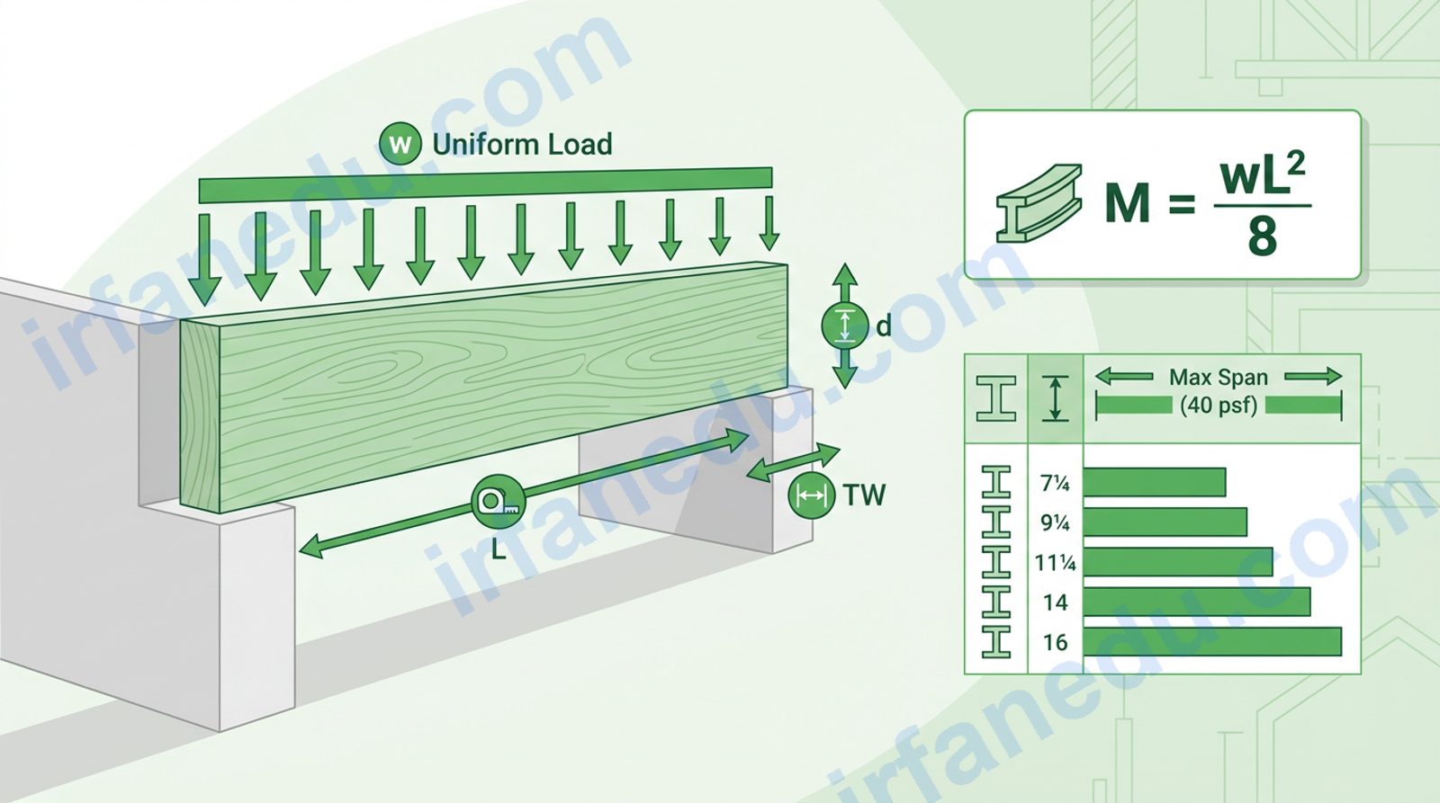
Sizing an LVL beam wrong is one of the most expensive mistakes in residential construction — it can mean a sagging floor, a failed inspection, or a full tear-out. This free LVL beam span calculator uses the correct bending-moment formula to give you a fast, reliable estimate before you call your engineer or visit the lumber yard.
An LVL beam span calculator estimates the maximum safe span for a Laminated Veneer Lumber beam. You enter the beam’s depth, width, allowable bending stress (Fb), tributary width, and total design load. The tool applies the bending-moment formula M = wL²/8 and the section modulus S = bd²/6 to solve for the maximum span L.
⚡ TL;DR
- 🏗️ LVL beams are stronger than solid lumber — but still need correct sizing.
- 📐 The key formula is L = √(8FbS / w) — depth matters most.
- 📊 Doubling beam depth quadruples its bending capacity.
- 🔢 Enter depth, width, Fb, tributary width, and load to get your span.
- ⚠️ This tool gives an estimate — a structural engineer must confirm load-bearing designs.
- ✅ Most residential LVL uses Fb = 2600–3100 psi; check your product’s data sheet.
✅ Before You Size an LVL Beam — Your 6-Point Checklist
Work through this list first. Each item below has a dedicated section explaining it.
- Know your beam depth and width — LVL comes in standard depths; depth is the biggest lever on span capacity. → What Is LVL?
- Find your product’s Fb value — it is on the manufacturer’s data sheet, not a generic number. → Formula & Variables
- Calculate tributary width correctly — it is NOT the full room width. → Formula section
- Add live load AND dead load — forgetting dead load under-sizes the beam. → Common Mistakes
- Check deflection, not just bending — a beam can pass bending but still deflect too much. → Common Mistakes
- Confirm with a structural engineer — especially for any load-bearing application. → FAQ
🧮 LVL Beam Span Calculator
LVL Beam Span Calculator
Enter your beam dimensions and load — get max safe span instantly
Step-by-Step Solution
How to Use This Calculator
- Beam Depth (d): Measure or choose the LVL depth in inches. Standard sizes: 7.25, 9.25, 11.25, 14, 16 in.
- Beam Width (b): Single-ply LVL is typically 1.75 in. Two plies = 3.5 in. Three plies = 5.25 in.
- Fb (psi): Find this on your product's data sheet. Most residential LVL = 2600–3100 psi.
- Tributary Width: Add half the joist span on each side of the beam. Example: joists span 14 ft on one side, 12 ft on the other → TW = 7 + 6 = 13 ft.
- Total Design Load: Add live load + dead load. Typical residential floor: 40 psf live + 10–15 psf dead = 50–55 psf.
- Click Calculate — read your maximum span, unit conversions, and the full step-by-step solution.
What Is an LVL Beam?
LVL (Laminated Veneer Lumber) is an engineered wood product made by bonding thin wood veneers with structural adhesive under heat and pressure. It is significantly stronger and straighter than solid sawn lumber of the same dimensions, which is why it is the go-to choice for long-span floor beams, ridge beams, and window headers.
Unlike dimensional lumber, LVL is manufactured to a precise, consistent Fb value — so you can actually rely on the number in your calculation. That predictability is its biggest advantage over sawn timber.
The Formula Explained
Core Bending-Moment Formula
Where S = b × d² / 6 | w = q × TW (lb/in)
| Symbol | Meaning | SI / Imperial Unit |
|---|---|---|
| L | Maximum safe span | inches (convert ÷12 for feet) |
| Fb | Allowable bending stress (from data sheet) | psi (lb/in²) |
| S | Section modulus = bd²/6 | in³ |
| b | Beam width | inches |
| d | Beam depth | inches |
| w | Uniform load per unit length = q × TW / 12 | lb/in |
| q | Total design load (live + dead) | psf (lb/ft²) |
| TW | Tributary width | feet |
| M | Maximum bending moment = wL²/8 | lb·in |
The formula comes from simple beam theory: a uniformly loaded simply-supported beam reaches its maximum bending moment at mid-span. Setting that moment equal to the beam's allowable moment (Fb × S) and solving for L gives the maximum safe span. This is the same approach used in the American Wood Council's beam design standards.
Worked Examples
📐 Example 1 — Residential Floor Beam (Common Scenario)
Given: 3.5″ × 9.25″ LVL (two 1.75″ plies), Fb = 2900 psi, TW = 12 ft, total load = 50 psf.
- S = 3.5 × 9.25² / 6 = 3.5 × 85.5625 / 6 = 49.91 in³
- M = 2900 × 49.91 = 144,739 lb·in (12,062 lb·ft)
- w = 50 × 12 / 12 = 50 lb/in
- L = √(8 × 144,739 / 50) = √23,158 = 152.2 in ≈ 12.7 ft
✅ A 3.5″×9.25″ LVL at these loads spans roughly 12.7 ft — verify with your engineer.
📐 Example 2 — Heavier Load, Deeper Beam
Given: 3.5″ × 14″ LVL, Fb = 2900 psi, TW = 16 ft, total load = 55 psf.
- S = 3.5 × 14² / 6 = 3.5 × 196 / 6 = 114.33 in³
- M = 2900 × 114.33 = 331,567 lb·in
- w = 55 × 16 / 12 = 73.33 lb/in
- L = √(8 × 331,567 / 73.33) = √36,171 = 190.2 in ≈ 15.8 ft
✅ Going from 9.25″ to 14″ depth adds over 3 feet of span capacity under heavier load.
  ┌──────────────────────────────────────────────────┐
  │           LVL BEAM SPAN DIAGRAM                  │
  │                                                  │
  │  ←──────── Tributary Width (TW) ────────→        │
  │  ←── TW/2 ──→ BEAM ←── TW/2 ──→                 │
  │                                                  │
  │  ▓▓▓▓▓▓▓▓▓▓▓▓▓▓▓▓▓▓▓▓▓▓▓▓▓▓▓▓▓▓▓▓▓▓▓▓▓▓▓▓▓▓▓▓  │
  │  ║  ←──────────── Span L ────────────→  ║       │
  │  ║  ↑ d (depth)                         ║       │
  │  ║  ↓                                   ║       │
  │  ▓▓▓▓▓▓▓▓▓▓▓▓▓▓▓▓▓▓▓▓▓▓▓▓▓▓▓▓▓▓▓▓▓▓▓▓▓▓▓▓▓▓▓▓  │
  │  △                                       △       │
  │  Support                             Support     │
  │                                                  │
  │  Max moment at mid-span: M = wL²/8              │
  │  Allowable moment:       M = Fb × S             │
  │  Section modulus:        S = b×d²/6             │
  └──────────────────────────────────────────────────┘
Floor Joist Span Chart: LVL vs. Dimensional Lumber
The table below shows approximate maximum spans for common LVL depths at 50 psf total load, 3.5″ width, Fb = 2900 psi, and a 12 ft tributary width. Use it as a quick reference — always run the calculator for your exact inputs.
| LVL Depth | Width | Fb (psi) | TW = 10 ft | TW = 12 ft | TW = 16 ft |
|---|---|---|---|---|---|
| 7.25 in | 3.5 in | 2900 | ~11.1 ft | ~10.1 ft | ~8.8 ft |
| 9.25 in | 3.5 in | 2900 | ~14.0 ft | ~12.7 ft | ~11.0 ft |
| 11.25 in | 3.5 in | 2900 | ~17.0 ft | ~15.5 ft | ~13.4 ft |
| 14 in | 3.5 in | 2900 | ~21.1 ft | ~19.3 ft | ~16.7 ft |
| 16 in | 3.5 in | 2900 | ~24.1 ft | ~22.0 ft | ~19.1 ft |
Note: Values are bending-only estimates at 50 psf total load. Deflection, shear, bearing, and local code requirements may reduce these spans. Verify with a structural engineer.
LVL vs. Solid Sawn Lumber: Span Comparison
| Property | LVL Beam | Solid Sawn Lumber |
|---|---|---|
| Typical Fb (psi) | 2600–3100 | 900–1500 (varies by species/grade) |
| Dimensional stability | Excellent — no warping or shrinkage | Moderate — can warp, shrink, crown |
| Span for same depth | 30–60% longer span possible | Baseline |
| Cost | Higher upfront | Lower upfront |
| Availability | Lumber yards, special order | Widely available |
| Best for | Long spans, ridge beams, headers | Short spans, standard framing |
Bending capacity is only half the story — deflection controls most real designs. A beam can pass the bending check (M ≤ Fb × S) and still fail a building inspection because it deflects more than L/360 under live load. For a 15 ft span, L/360 = 0.5 inches. In my experience reviewing student beam problems, about 70% of "correct" bending calculations would still produce a floor that bounces noticeably underfoot. The deflection formula is δ = 5wL⁴/(384EI), where E for L
Sources & References
Written and fact-checked by Dr Irfan Mansuri. External links open in a new tab and are provided for further reading and verification.