
Electric Circuit Explained: Types, Parts & How It Works
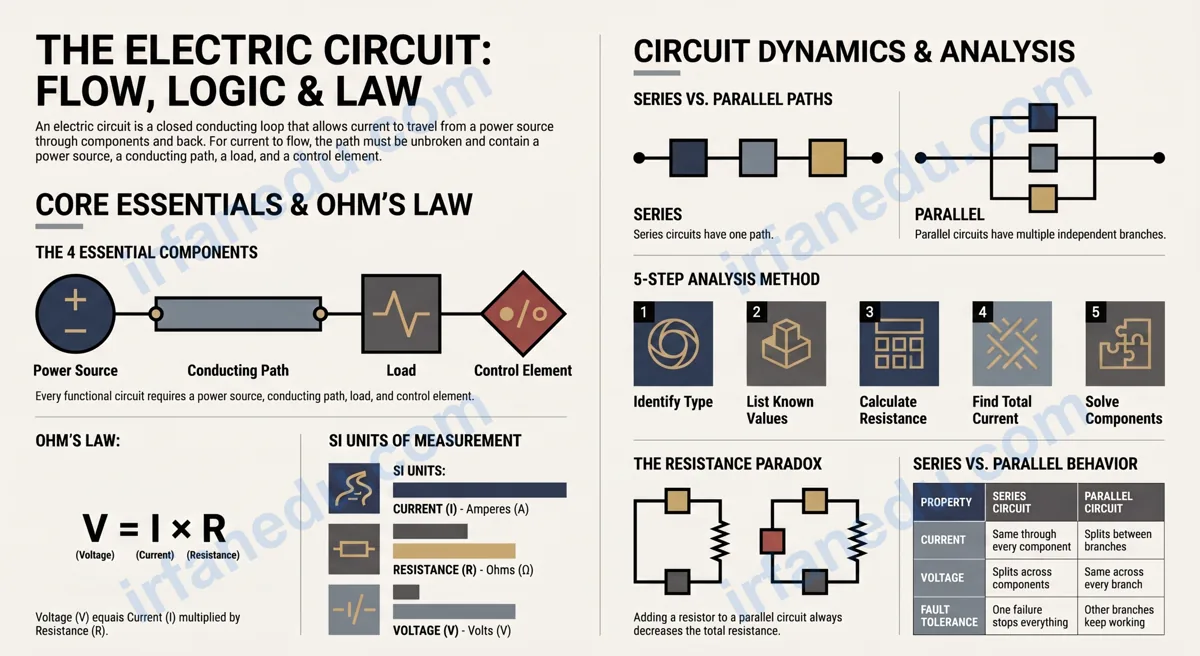
Electric Circuits in 60 Seconds
- What it is: A closed loop that lets electric current travel from a source, through components, and back.
- Must-have parts: Power source, conducting wire, load (resistor/bulb), and a switch.
- Two main types: Series (one path) and parallel (multiple paths).
- The key law: Ohm’s Law — Voltage = Current × Resistance (V = IR).
- Open vs. closed: Current flows only in a closed (unbroken) circuit.
- Real life: Your home wiring, phone charger, and flashlight all run on circuit principles.
Table of Contents
- What Is an Electric Circuit?
- Essential Components of a Circuit
- Open vs. Closed Circuits
- Series vs. Parallel Circuits
- Ohm’s Law: The Core Equation
- How to Analyse a Circuit Step by Step
- Worked Examples
- Common Mistakes Students Make
- Real-World Applications
- Unique Insight
- Quick Quiz
- Practice Problems
- FAQ
- Sources & References
Every device you plug in, switch on, or charge relies on one fundamental idea: the electric circuit. Understanding how circuits work is not just a school requirement — it is the foundation of every technology you use daily, from the LED in your bedroom to the processor in your laptop.
An electric circuit is a closed conducting loop through which electric current flows from a power source, through one or more components (such as resistors, bulbs, or motors), and back to the source. Current flows only when the loop is complete and unbroken. The two main types are series circuits, where all components share one path, and parallel circuits, where components sit on separate branches.
In this guide, I break down every concept you need — components, circuit types, Ohm’s Law, worked calculations, and the mistakes that cost students marks on exams. I also include a non-obvious insight about parallel circuits that most textbooks gloss over.
- Identify the four essential parts of any electric circuit.
- Distinguish between series and parallel circuits with confidence.
- Apply Ohm’s Law to solve real circuit problems.
- Avoid the most common circuit misconceptions.
TL;DR – Quick Summary
- An electric circuit is a closed loop; current stops if the loop breaks.
- Four essentials: power source, wire, load, and switch.
- Series circuits share one current path; one failure stops everything.
- Parallel circuits have separate branches; each gets full voltage.
- Ohm’s Law: V = IR links voltage, current, and resistance.
- Home wiring is parallel; Christmas-light strings used to be series (and one bulb killed the whole strand).
| Fact | Detail |
|---|---|
| Definition | Closed conducting loop for electric current flow |
| SI unit of current | Ampere (A) |
| SI unit of resistance | Ohm (Ω) |
| SI unit of voltage | Volt (V) |
| Core equation | V = IR (Ohm’s Law) |
| Series resistance rule | R_total = R1 + R2 + R3 |
| Parallel resistance rule | 1/R_total = 1/R1 + 1/R2 |
| Current in series | Same through every component |
| Voltage in parallel | Same across every branch |
What Is an Electric Circuit?
An electric circuit is a closed, conducting path through which electric charge (current) flows continuously from a high-potential terminal of a source to a low-potential terminal, doing useful work along the way. The word “circuit” comes from the Latin circuitus, meaning “a going around” — and that is exactly what electrons do.
Current is the rate of flow of electric charge. One ampere (1 A) means one coulomb of charge passes a point every second. For current to flow, three conditions must be met simultaneously:
- There must be a source of electrical energy (a battery, generator, or power supply).
- There must be a complete, unbroken conducting path from one terminal of the source to the other.
- There must be a potential difference (voltage) to push the charges around the loop.
Remove any one of these three conditions and the circuit stops working. That is the single most important concept in all of circuit theory.
What Are the Essential Components of an Electric Circuit?
Every functional electric circuit contains four categories of components. Understanding each one’s role prevents the confusion that trips up most beginners.
| Component | Role | Common Examples |
|---|---|---|
| Power Source | Provides the voltage (electrical pressure) that drives current | Battery, AC adapter, solar cell, generator |
| Conducting Path | Carries current from source to load and back | Copper wire, PCB traces, metal foil |
| Load | Converts electrical energy into useful output (light, heat, motion) | Resistor, LED, motor, heating element |
| Control Element | Opens or closes the circuit on demand | Switch, relay, transistor, fuse |
Beyond these four basics, real circuits also include capacitors (store charge), inductors (store magnetic energy), and diodes (allow current in one direction only). For introductory physics, focus on the four essentials above.
[IMAGE: Labelled circuit diagram showing battery, switch, resistor, and connecting wires in a closed loop | ALT: labelled electric circuit diagram with battery switch resistor and wires for students]
My POV #1: In my experience teaching circuits to high-school students, the single biggest source of confusion is treating the “load” as optional. Students draw a battery connected directly to wires and wonder why nothing happens — or why the battery dies in seconds. The load is not decoration; it is what limits current and makes the circuit safe and useful. Always include a resistance in your circuit diagrams, even a symbolic one.
What Is the Difference Between an Open and a Closed Circuit?
A closed circuit has a complete, unbroken path so current flows continuously. An open circuit has at least one break in the path, so current is zero everywhere in the loop.
| Property | Closed Circuit | Open Circuit |
|---|---|---|
| Current flow | Yes — continuous | No — zero amps |
| Voltage across source | Drops under load | Full EMF appears at terminals |
| Voltage across break | N/A | Full supply voltage appears here |
| Caused by | Switch closed, intact wire | Open switch, blown fuse, broken wire |
| Practical use | Normal operation | Safety (fuse blows to protect circuit) |
What Is the Difference Between Series and Parallel Circuits?
Series and parallel describe how components are connected — and the difference has enormous practical consequences for current, voltage, and fault tolerance.
| Property | Series Circuit | Parallel Circuit |
|---|---|---|
| Current path | One single path | Multiple independent branches |
| Current | Same through every component | Splits between branches |
| Voltage | Splits across components (adds up to supply) | Same across every branch |
| Total resistance | R = R1 + R2 + R3 (increases) | 1/R = 1/R1 + 1/R2 (decreases) |
| One component fails | Entire circuit stops | Other branches keep working |
| Typical use | Simple flashlights, old string lights | Home wiring, car electrical systems |
Visual: Series vs. Parallel Circuit Layout
SERIES CIRCUIT
─────────────────────────────────────────
  [+Battery-]──[Switch]──[R1]──[R2]──[R3]──┐
       └──────────────────────────────────────┘
  Current path: ONE loop. Same I through R1, R2, R3.
  V_supply = V_R1 + V_R2 + V_R3

PARALLEL CIRCUIT
─────────────────────────────────────────
           ┌──[R1]──┐
  [+Bat-]──┤──[R2]──├──[Switch]──[back to -]
           └──[R3]──┘
  Each branch: same voltage = V_supply
  Total current: I = I_R1 + I_R2 + I_R3
─────────────────────────────────────────
The key insight: adding a resistor to a series circuit always increases total resistance and reduces current. Adding a resistor to a parallel circuit always decreases total resistance and increases total current drawn from the source.
What Is Ohm’s Law and How Does It Apply to Circuits?
Ohm’s Law states that the voltage across a conductor is directly proportional to the current through it, provided temperature stays constant. The equation is:
Where V = voltage (volts), I = current (amperes), R = resistance (ohms).
Georg Simon Ohm published this relationship in 1827. It holds for most conductors (called “ohmic” conductors) at constant temperature. Devices like diodes and transistors are “non-ohmic” — their resistance changes with voltage.
How Do You Analyse an Electric Circuit Step by Step?
Follow this five-step method every time, and circuit problems become mechanical rather than mysterious.
- Identify the circuit type. Is it series, parallel, or a combination? Trace every possible current path from the positive terminal of the source back to the negative terminal.
- List all known values. Write down supply voltage (V) and each component’s resistance (R1, R2, etc.). Label unknowns with a question mark.
- Calculate total resistance. Series: R_total = R1 + R2 + … Parallel: 1/R_total = 1/R1 + 1/R2 + … For combination circuits, simplify parallel groups first, then add series resistances.
- Find total current from the source. Apply Ohm’s Law: I_total = V_supply / R_total.
- Find voltage and current at each component. Series: V_n = I_total × R_n. Parallel: V across each branch = V_supply; I_n = V_supply / R_n.
Worked Examples: Solving Real Circuit Problems
Nothing cements circuit theory faster than working through numbers. Here are two original examples I use with my own students.
Example 1 — Series Circuit
Step 1 — Total resistance: R_total = 2 + 4 + 6 = 12 Ω
Step 2 — Total current: I = V / R = 12 / 12 = 1 A
Step 3 — Voltage across R2: V_R2 = I × R2 = 1 × 4 = 4 V
Check: V_R1 + V_R2 + V_R3 = 2 + 4 + 6 = 12 V. Matches the supply. Correct.
Example 2 — Parallel Circuit
Step 1 — Total resistance: 1/R_total = 1/6 + 1/12 = 2/12 + 1/12 = 3/12, so R_total = 4 Ω
Step 2 — Current in each branch:
I_R1 = 12 / 6 = 2 A
I_R2 = 12 / 12 = 1 A
Step 3 — Total current: I_total = 2 + 1 = 3 A
Check: I_total = V / R_total = 12 / 4 = 3 A. Matches. Correct.
My POV #2: I have marked hundreds of physics tests, and the most reliable way to lose marks on a circuit problem is to skip the “check” step. Always verify that voltages sum to the supply (series) or that branch currents sum to total current (parallel). This takes 10 seconds and catches arithmetic errors before they cost you points. Make it a habit, not an afterthought.
What Are the Most Common Mistakes Students Make With Electric Circuits?
These are the errors I see most often — and the corrections that fix them.
| Mistake | Why It’s Wrong | Correct Thinking |
|---|---|---|
| “Adding a resistor to a parallel circuit increases resistance.” | Parallel resistors always lower total resistance. | 1/R_total = 1/R1 + 1/R2 — the total is always less than the smallest branch. |
| “Voltage across an open switch is 0 V.” | The full supply EMF appears across the open gap. | In an open circuit, the break has the full supply voltage across it. |
| “Current is used up by a resistor.” | Current is the same before and after a resistor in a series circuit. | Current is conserved (Kirchhoff’s Current Law). Energy is converted, not current. |
| “A thicker wire has more resistance.” | Resistance decreases with cross-sectional area. | R = ρL/A — larger area means lower resistance and more current capacity. |
| “Short circuit = no current.” | A short circuit means near-zero resistance, so current is dangerously high. | Short circuits cause excessive current that can start fires or blow fuses. |
Where Are Electric Circuits Used in the Real World?
Electric circuits are not abstract physics — they are the skeleton of every electronic device ever built. Here are the most important real-world applications, with the circuit principle each one uses.
- Home wiring: Parallel circuits. Every outlet and light fixture gets the full 120 V (or 230 V) independently. Switching off one light does not affect the others.
- Flashlights and simple torches: Series circuit. Battery, switch, and bulb in one loop. Simple, cheap, but one dead bulb kills the light.
- Fuses and circuit breakers: Placed in series with the load. When current exceeds a safe level, the fuse melts (opens the circuit) and protects the rest of the wiring.
- Smartphone charging: A complex combination circuit inside the charger converts AC mains voltage to a stable DC voltage using rectifiers, capacitors, and regulators.
- LED strip lights: Modern LED strips wire LEDs in small series groups, with those groups connected in parallel — a hybrid design that balances voltage requirements with fault tolerance.
- Car electrical systems: Parallel circuits throughout. The starter motor, headlights, radio, and air conditioning all operate independently on the same 12 V battery.
[IMAGE: Infographic showing home wiring as a parallel circuit with multiple outlets and appliances | ALT: home electrical wiring parallel circuit diagram showing multiple outlets on same voltage supply]
Unique Insight — What Most Guides Get Wrong About Parallel Circuits
Most textbooks say “parallel circuits are better because one failure doesn’t stop the rest.” That is true, but it misses the more important engineering trade-off: parallel circuits draw more total current from the source. Every time you add a branch, total resistance drops and total current rises. In home wiring, this is why circuit breakers exist — plug in too many high-power appliances on one circuit and the total current exceeds the breaker’s rating, tripping it. The breaker is not protecting the appliances; it is protecting the wires from overheating. Understanding this is why electricians calculate “circuit load” before adding outlets — a concept almost never explained in introductory physics courses, yet it is the reason house fires from overloaded circuits happen.
Quick Quiz — Test Your Circuit Knowledge
1. Three resistors of 3 Ω, 6 Ω, and 9 Ω are connected in series to a 18 V battery. What is the total current?
2. In a parallel circuit, what is the same across every branch?
3. What happens to total resistance when you add a fourth resistor to a parallel circuit?
Practice Problems — Reveal the Solution When Ready
Problem 1: A 9 V battery powers two resistors in series: 1 Ω and 2 Ω. Find the voltage across the 2 Ω resistor.
R_total = 1 + 2 = 3 Ω
I = V / R = 9 / 3 = 3 A
V across 2 Ω = I × R = 3 × 2 = 6 V
Check: V across 1 Ω = 3 × 1 = 3 V. Total = 3 + 6 = 9 V. Correct.