
SPDT switch explained: how it works, wiring & real uses
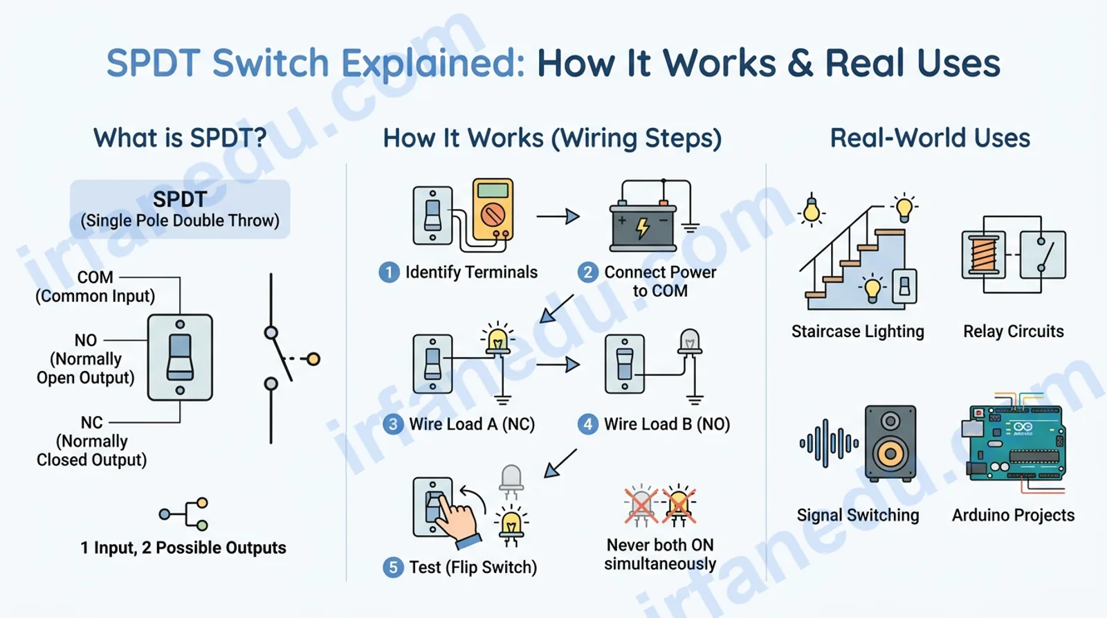
What exactly does an SPDT switch do, and why does it have three terminals instead of two? An SPDT switch routes one input signal to one of two possible outputs — it is the electrical equivalent of a fork in the road. You see it every time you flip a staircase light switch, change guitar amp channels, or build an Arduino project that needs to choose between two circuits.
An SPDT (Single Pole Double Throw) switch is a three-terminal switching device. One terminal — called COM (Common) — is the shared input. The other two terminals — NO (Normally Open) and NC (Normally Closed) — are the two possible outputs. Flipping the switch disconnects COM from one output and connects it to the other. Only one output is active at any given moment.
- The exact function of each SPDT terminal (COM, NO, NC)
- How to read and draw the SPDT circuit symbol
- Step-by-step wiring of a two-lamp SPDT circuit
- How SPDT compares to SPST, DPDT, and other switch types
- Real-world applications from staircase lighting to Arduino
- The one wiring mistake most beginners make (and how to avoid it)
An SPDT switch (Single Pole Double Throw) is a three-terminal switch with one common input and two output positions. Flipping it connects the COM terminal to either the NO (Normally Open) or NC (Normally Closed) output — never both at once. It routes a single power line or signal to one of two destinations, making it essential for staircase lighting, relay circuits, and signal-switching applications.
- ⚡ SPDT = Single Pole Double Throw — one input, two possible outputs.
- 🔌 Three terminals: COM (input), NO (open by default), NC (closed by default).
- 🔄 Flipping the switch transfers COM from NC to NO — or back again.
- 🏠 Classic use: staircase lighting controlled from two locations.
- 🔧 Can substitute for an SPST by leaving one output terminal unconnected.
- 📐 Circuit symbol shows a pivoting arm between two contact points.
How to wire an SPDT switch: step-by-step
Wiring an SPDT switch is straightforward once you know which terminal does what. Follow these five steps to build a working two-lamp circuit — the most common beginner project.
Before you start, gather: one SPDT switch, one 9 V battery, two LEDs (or small lamps), two current-limiting resistors (470 Ω for 9 V), and connecting wires.
- Identify the three terminals. Look at the switch body or its datasheet. The center terminal is almost always COM. The two outer terminals are NO and NC. If unlabeled, use a multimeter in continuity mode: in the default (un-actuated) position, COM and NC will beep; COM and NO will not.
- Connect your power source to COM. Run a wire from the positive rail of your 9 V battery to the COM terminal. This is your single input — the “pole.”
- Wire Load A (LED 1) to the NC terminal. Connect one leg of LED 1 (through its resistor) to the NC terminal. Run the other leg back to the battery’s negative rail. LED 1 is now ON by default because NC is already connected to COM at rest.
- Wire Load B (LED 2) to the NO terminal. Connect LED 2 (through its resistor) from the NO terminal back to the negative rail. LED 2 is OFF by default because NO is open at rest.
- Test and verify. With the switch un-actuated: LED 1 on, LED 2 off. Flip the switch: LED 1 off, LED 2 on. Flip back: LED 1 on again. At no point are both LEDs on simultaneously — that is the defining behavior of an SPDT switch.
  +9V ──────────────┬──────────────────────────────────────────────┐
                    │                                              │
                   COM                                            │
                 ╔══╧══╗                                          │
                 ║ SPDT║                                          │
                 ╚══╤══╝                                          │
               NC ──┤── NO                                        │
               │         │                                        │
              [R1]       [R2]                                      │
               │         │                                        │
             [LED1]    [LED2]                                      │
               │         │                                        │
  GND ─────────┴─────────┴──────────────────────────────────────GND

  Default (switch un-actuated):
    COM ──► NC ──► LED1 ON   |   NO open ──► LED2 OFF

  After flip (switch actuated):
    COM ──► NO ──► LED2 ON   |   NC open ──► LED1 OFF
Never connect a load between NO and NC directly. Those are both outputs — they should each connect independently back to the negative rail (ground). Bridging them creates a short circuit when the switch transfers.
What is an SPDT switch?
An SPDT switch is a three-terminal electromechanical device that connects one common input to one of two possible outputs. The name encodes its entire behavior: “Single Pole” means it controls exactly one circuit path (one input), and “Double Throw” means the actuating arm can be thrown to either of two positions.
Think of it as a railway switch (points). A train (current) arrives on a single track (COM). The switch directs it onto either Track A (NC) or Track B (NO) — never both. The train cannot split; it must go one way.
An SPDT switch is a switching device with three terminals — COM, NO, and NC — that routes one input signal to one of two outputs by mechanically transferring a contact arm between two positions. It is classified by its pole count (1) and throw count (2).
What do COM, NO, and NC mean?
These three labels appear on every SPDT switch, relay, and datasheet. Understanding them is non-negotiable:
- COM (Common): The single input terminal. Current or signal always enters here. It is “common” because it is shared between both output paths.
- NC (Normally Closed): The output that is connected to COM when the switch is in its default, un-actuated (resting) state. “Normally” refers to the no-power / no-force condition.
- NO (Normally Open): The output that is disconnected from COM in the default state. It only connects to COM when the switch is actively actuated (pressed, flipped, or energized).
In my experience teaching circuits, the single biggest source of confusion is the word “Normally.” Students read “Normally Open” and assume it means the switch is broken or faulty. It is not. “Normal” means the default resting state — no finger pressing it, no coil energized. Once you anchor that definition, the whole SPDT concept clicks into place instantly.
What does the SPDT switch circuit symbol look like?
The SPDT circuit symbol shows a single input line (COM) connected to a pivoting arm — the “throw” — that can rest on either of two output contact points. In the default position, the arm touches the NC contact. When actuated, it lifts and touches the NO contact.
         NC ──●
              ╲
   COM ────────○    ← pivoting arm (throw)
              ╱
         NO ──●

  ● = fixed contact point
  ○ = pivot / COM terminal
  ╲ = arm in default (NC) position
In a schematic, you will see the arm drawn as a diagonal line touching one of the two output dots. A small circle at the pivot marks the COM terminal. Some schematics add a dashed line between the two contacts to indicate they are part of the same switch unit.
How does SPDT compare to SPST, DPST, and DPDT?
Switch types are named using a consistent pole-and-throw notation. Here is how SPDT sits among the most common types:
| Switch type | Poles | Throws | Terminals | What it does | Typical use |
|---|---|---|---|---|---|
| SPST | 1 | 1 | 2 | Opens or closes one circuit | Simple on/off (lamp, fan) |
| SPDT | 1 | 2 | 3 | Routes one input to one of two outputs | Staircase light, signal selector |
| DPST | 2 | 1 | 4 | Opens/closes two circuits simultaneously | Mains power (switch live + neutral) |
| DPDT | 2 | 2 | 6 | Routes two inputs each to one of two outputs | Motor direction reversal, H-bridge |
A useful rule: number of terminals = poles × (throws + 1). For SPDT: 1 × (2 + 1) = 3 terminals. For DPDT: 2 × (2 + 1) = 6 terminals. This formula works for all standard switch types.
Worked example: staircase lighting with two SPDT switches
The staircase lighting problem is the classic SPDT application in physics and electrical engineering courses. The goal: one light, controlled from two separate locations (bottom and top of the stairs). Either switch must be able to turn the light on or off, regardless of the other switch’s position.
The setup
You need two SPDT switches (Switch A at the bottom, Switch B at the top), one lamp, and a power supply. Connect them like this:
- Connect the power supply positive rail to COM of Switch A.
- Connect NO of Switch A to NO of Switch B using a wire (Traveler Wire 1).
- Connect NC of Switch A to NC of Switch B using a second wire (Traveler Wire 2).
- Connect COM of Switch B to one terminal of the lamp.
- Connect the other lamp terminal back to the power supply negative rail.
  +V ──── COM(A)
              ├── NC(A) ──── Traveler 2 ──── NC(B) ──┐
              └── NO(A) ──── Traveler 1 ──── NO(B) ──┤
                                                  COM(B) ──── [LAMP] ──── GND

  Switch A: DOWN = NC active | UP = NO active
  Switch B: DOWN = NC active | UP = NO active

  State table:
  ┌──────────┬──────────┬────────────────────────────────┬───────┐
  │ Switch A │ Switch B │ Active path                    │ Lamp  │
  ├──────────┼──────────┼────────────────────────────────┼───────┤
  │ DOWN(NC) │ DOWN(NC) │ COM(A)→NC(A)→T2→NC(B)→COM(B)  │  ON   │
  │ DOWN(NC) │ UP  (NO) │ NC(A)→T2→NC(B) — B is on NO   │  OFF  │
  │ UP  (NO) │ DOWN(NC) │ NO(A)→T1→NO(B) — B is on NC   │  OFF  │
  │ UP  (NO) │ UP  (NO) │ COM(A)→NO(A)→T1→NO(B)→COM(B)  │  ON   │
  └──────────┴──────────┴────────────────────────────────┴───────┘
Notice the pattern: the lamp is ON when both switches are in the same position (both NC or both NO). Flipping either switch changes the lamp state. This is electrically equivalent to an XNOR logic gate — a fact that surprises most students.
The two traveler wires are not “live” and “neutral” — they are both signal paths that alternate between carrying current and being open. This is why standard two-wire cable is not suitable for staircase wiring; you need three-wire cable (two travelers + ground).
Where is an SPDT switch used in real life?
SPDT switches appear in far more places than most students realize. Here are the most common real-world applications, each explained in plain terms:
- Staircase and hallway lighting: The most textbook example. Two SPDT switches at opposite ends of a corridor let you control one light from either location.
- Guitar amplifier channel selector: A footswitch uses an SPDT to route the guitar signal to either the clean channel or the overdrive channel. Only one channel is active at a time.
- Car headlight high/low beam selector: The stalk on your steering column uses an SPDT-style mechanism to route power to either the high-beam or low-beam filament.
- Relay circuits in automation: Electromechanical relays are essentially electrically-actuated SPDT switches. When the coil is energized, the armature transfers from NC to NO — allowing a small control signal to switch a large load.
- Arduino and microcontroller projects: SPDT switches route signals between two input pins or select between two operating modes without needing extra logic gates.
- HVAC thermostats: Older thermostats use an SPDT mechanism to switch between heating and cooling modes — COM connects to the power supply, NC drives the heater, NO drives the air conditioner.
In my experience building classroom demonstrations, the relay is the most underappreciated SPDT application. Students are always surprised to learn that the relay in a car’s fuse box — controlling the starter motor — is just an SPDT switch with an electromagnet as its actuator. Understanding SPDT makes relay logic immediately intuitive, which then unlocks programmable logic controllers (PLCs) and industrial automation concepts.
Common mistakes students make with SPDT switches
These are the errors I see most often in lab reports and circuit assignments — and the correct approach for each:
| ❌ Wrong approach | ✅ Correct approach |
|---|---|
| Treating NO as “broken” or “faulty” because nothing happens in default state | NO is intentionally open at rest — it activates only when the switch is thrown |
| Connecting both loads between NO and NC (bridging the outputs) | Each load connects independently from its output terminal back to ground |
| Using only COM and NO, then wondering why the circuit is always off at rest | If you want a default-ON circuit, use COM and NC; default-OFF, use COM and NO |
| Confusing “pole” with “throw” when naming switch types | Pole = number of independent inputs; Throw = number of positions per pole |
| Assuming SPDT and SPST are interchangeable | SPDT can substitute for SPST (leave one terminal open), but not vice versa |
The SPDT is a logic gate in disguise — and most guides never mention this.
When you wire two SPDT switches in the staircase configuration, the lamp’s on/off state is determined by whether the two switches are in the same position or different positions. That is the exact truth table of an XNOR gate (output HIGH when inputs match). This means you can build basic combinational logic — without any transistors or ICs — using only SPDT switches and a lamp.
Taking it further: three-way switching (three locations controlling one lamp) requires adding a DPDT switch in the middle of the traveler wires. The DPDT acts as an XOR stage. This is how hotels and large stairwells wire multi-point lighting control — pure relay logic, no microcontrollers needed.
In my experience, students who grasp this connection between mechanical switches and Boolean logic find digital electronics dramatically easier to learn. The SPDT is not just a wiring component — it is a physical AND/OR/XNOR gate you can hold in your hand.
Practice problems: test your understanding
Work through these problems yourself, then click to reveal the solution.
Problem 1 — Identify the active path: Switch A is on NC, Switch B is on NO. Is the staircase lamp on or off?
Solution: Switch A routes COM(A) to NC(A). The NC traveler wire connects NC(A) to NC(B). But Switch B is currently on NO — meaning COM(B) is connected to NO(B), not NC(B). The NC traveler wire arrives at NC(B) but cannot reach COM(B). The circuit is broken. The lamp is OFF.
This matches row 2 of the state table: Switch A DOWN (NC), Switch B UP (NO) → Lamp OFF.
Problem 2 — Terminal identification: You have an unlabeled SPDT switch. In the default position, your multimeter shows continuity between Pin 1 and Pin 2, but not between Pin 1 and Pin 3. Which pin is COM, which is NC, and which is NO?
Solution: In the default (un-actuated) state, COM is always connected to NC. Pin 1 has continuity with Pin 2, so either Pin 1 is COM and Pin 2 is NC, or Pin 2 is COM and Pin 1 is NC.
To distinguish COM from NC: actuate the switch (press/flip it) and re-test. After actuation, COM connects to NO. If Pin 1 now shows continuity with Pin 3 (and not Pin 2), then Pin 1 = COM, Pin 2 = NC, Pin 3 = NO. If Pin 2 shows continuity with Pin 3, then Pin 2 = COM, Pin 1 = NC, Pin 3 = NO.
Problem 3 — Design challenge: You need to control a motor from three separate locations. How many switches do you need, and what types?
Solution: For three-location control you need two SPDT switches (at the two end locations) and one DPDT switch (at the middle location). The two SPDT switches handle the end points exactly like staircase wiring. The DPDT in the middle acts as a “crossover” switch — it either passes the traveler wires straight through or crosses them over, effectively inserting an XOR operation into the circuit. This is the standard three-way (and four-way) switching scheme used in building wiring worldwide.
Frequently asked questions about SPDT switches
What does SPDT stand for?
What is the difference between SPDT and SPST?
What are the three terminals of an SPDT switch?
Where is an SPDT switch used in real life?
Can an SPDT switch work as an SPST switch?
What is the circuit symbol for an SPDT switch?
- SPDT = Single Pole Double Throw — one input (COM), two outputs (NO and NC), three terminals total.
- “Normally” refers to the default un-actuated state, not a fault condition.
- Flipping the switch transfers COM from NC to NO — only one output is active at any time.
- The staircase lighting circuit uses two SPDT switches wired with two traveler wires — it is electrically an XNOR gate.
- SPDT can substitute for SPST by leaving one output terminal unconnected.
- Relays are electrically-actuated SPDT switches — understanding SPDT unlocks relay and PLC logic.
- The terminal count formula: poles × (throws + 1) works for all standard switch types.
Sources & references
- Wikipedia — Switch (electrical): comprehensive overview of switch types, pole-and-throw notation, and circuit symbols.
- Electronics Tutorials — Input/Output Devices: Switches: detailed explanation of SPST, SPDT, DPDT switch types with circuit diagrams.
- SparkFun Learn —