
⚙️ Electric Motor Design: How It Works, Key Components & the Physics Behind Every Spin
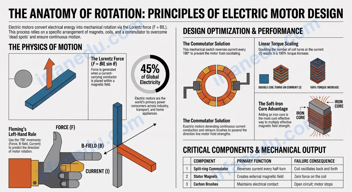
If you have ever wondered why a fan blade spins, why an electric car accelerates silently, or how a tiny motor inside your phone vibrates — the answer is electric motor design. It is one of the most elegant applications of physics: a simple loop of wire, a pair of magnets, and a clever switching trick combine to turn electricity into endless rotation.
In my experience teaching this topic, students who truly understand why each component exists — not just what it is called — score significantly better on exams and actually enjoy the subject. This guide starts with the most-asked question and builds outward from there.
Electric motor design is the arrangement of a current-carrying coil, a magnetic field, and a commutator so that the Lorentz force creates continuous rotational motion. The key insight is that the commutator reverses current every half-turn, keeping the torque in one direction and sustaining spin indefinitely.
- 🎯 Understand what each motor component actually does (and why removing any one stops the motor)
- 🔬 Apply the Lorentz force equation and Fleming’s Left-Hand Rule to real problems
- ⚙️ Know how to improve motor performance by changing design variables
- ❌ Avoid the three most common exam mistakes about commutators and torque
- 🌍 Connect motor physics to real-world devices you use every day
Electric motor design is the arrangement of a current-carrying coil (armature), permanent magnets (stator), a split-ring commutator, and carbon brushes so that the Lorentz force (F = BIL) creates continuous torque and rotation. Reversing current direction or magnetic field polarity reverses the spin direction. The commutator is the critical switching device that keeps rotation going in one direction.
⚡ TL;DR – Quick Summary
- 🔋 A motor converts electrical energy into mechanical rotation via the Lorentz force.
- 🧲 Five core parts: coil, stator magnets, commutator, brushes, and power supply.
- 🔄 The split-ring commutator reverses current every 180° to sustain continuous spin.
- 📐 Fleming’s Left-Hand Rule predicts force direction on each conductor in the field.
- ⬆️ Stronger magnet, more coil turns, or higher current each increase torque.
- ⚠️ The coil produces zero torque at the exact moment it is parallel to the field — the commutator bridges this dead spot.
| Feature | Detail |
|---|---|
| Energy conversion | Electrical → Mechanical (rotational) |
| Core principle | Lorentz force: F = BIL sin θ |
| Key switching device | Split-ring commutator |
| Direction rule | Fleming’s Left-Hand Rule |
| Typical school type | Simple DC motor (rectangular coil) |
| Reverse rotation method | Reverse current OR reverse field (not both) |
| Real-world examples | Fans, EVs, hard drives, power tools, drones |
What Is Electric Motor Design?
Electric motor design is the deliberate arrangement of electromagnetic components to convert electrical energy into continuous rotational mechanical energy. At its core, the design solves one engineering problem: how do you make a force that pushes a wire in one direction keep pushing in the same rotational direction as the wire moves?
The answer is the commutator — a switching device that reverses current direction every half-turn so the force always acts to rotate the coil the same way. Every other design choice (coil shape, magnet strength, number of turns) amplifies the basic effect.
The concept dates to Michael Faraday’s 1821 homopolar motor — the first demonstration that a current-carrying wire rotates around a magnet. Modern motors are far more complex, but every one of them still relies on the same Lorentz force Faraday discovered.
► MY POV: In my experience, the biggest conceptual leap students need to make is this: a motor does not just “use electricity.” It exploits a very specific interaction between a magnetic field and moving charges. Once you see it that way, every component makes perfect logical sense — and you stop memorizing and start understanding.
What Are the Main Components of an Electric Motor?
A simple DC electric motor has five essential components. Remove any one of them and the motor stops working entirely.
| Component | What It Does | Why It Is Essential |
|---|---|---|
| 🔁 Armature coil | Carries current in the magnetic field | The Lorentz force acts on this conductor to produce torque |
| 🧲 Stator magnets | Create the external magnetic field | No field = no force on the coil |
| 🔄 Split-ring commutator | Reverses current every 180° | Keeps torque in one rotational direction |
| ⚡ Carbon brushes | Maintain electrical contact with spinning commutator | Connects the stationary circuit to the rotating coil |
| 🔋 DC power supply | Drives current through the coil | No current = no force |
Many school-level motors also include a soft-iron core inside the coil. This concentrates the magnetic field lines, dramatically increasing the force on the coil without changing the current or the magnets.
🖼️ Visual: DC Motor Cross-Section (ASCII Diagram)
     N pole                    S pole
      |                          |
      |   +----[coil]----+        |
      |   |   (armature) |        |
      |   |               |       |
      |   +---[iron core]-+       |
      |         |    |            |
      |      [comm.][comm.]       |
      |       /          \        |
      |  [brush-]      [+brush]   |
      |      |              |     |
      +------+----[battery]--+----+
             (–)            (+)

  N = North pole of stator magnet
  S = South pole of stator magnet
  comm. = split-ring commutator halves
  brush = carbon brush (stationary contact)
How Does an Electric Motor Work? (Step-by-Step)
An electric motor works by passing current through a coil inside a magnetic field, generating a force on each side of the coil that creates a turning effect (torque), with the commutator ensuring the torque always acts in the same rotational direction.
Here is the exact sequence of events in one full rotation:
- Current flows in: The battery drives conventional current from the positive terminal through one carbon brush into one half of the commutator, then into the coil.
- Force on the left side: The left conductor of the coil carries current in one direction inside the magnetic field. The Lorentz force pushes it upward (or downward — depends on current and field direction).
- Force on the right side: The right conductor carries current in the opposite direction, so the Lorentz force pushes it in the opposite direction to the left side.
- Torque created: These two opposite forces on opposite sides of the coil create a net turning effect — the coil rotates.
- Coil reaches vertical (90°): The coil is now perpendicular to the field. Torque is at its maximum here.
- Coil reaches horizontal again (180°): The coil is now parallel to the field. Torque drops to zero — this is the “dead spot.” Momentum carries it through.
- Commutator switches: At exactly 180°, the two commutator halves swap contact with the brushes. This reverses the current direction in the coil.
- Rotation continues: The reversed current means the forces on each side swap — but because the coil has also flipped, the torque still acts in the same rotational direction. The coil keeps spinning.
What Force Makes an Electric Motor Spin?
The Lorentz force makes an electric motor spin. It is the force experienced by a current-carrying conductor placed inside a magnetic field, and it is described by the equation:
📐 The Motor Force Equation
F = BIL sin θ
- F = force on the conductor (Newtons, N)
- B = magnetic field strength (Tesla, T)
- I = current in the conductor (Amperes, A)
- L = length of the conductor in the field (metres, m)
- θ = angle between the conductor and the magnetic field
Force is maximum when θ = 90° (conductor perpendicular to field) and zero when θ = 0° (conductor parallel to field).
✏️ Worked Example: Calculate the Force on a Motor Coil
Problem: A motor coil has a conductor of length 0.05 m carrying a current of 2 A. It sits in a magnetic field of strength 0.3 T, perpendicular to the field (θ = 90°). What is the force on that conductor?
Solution:
- Write the formula: F = BIL sin θ
- Substitute values: F = 0.3 × 2 × 0.05 × sin 90°
- sin 90° = 1, so: F = 0.3 × 2 × 0.05 × 1
- F = 0.03 N
This 0.03 N force acts on one side of the coil. The opposite side experiences an equal force in the opposite direction, creating a torque that spins the motor.
How Does the Commutator Keep the Motor Spinning?
The split-ring commutator keeps the motor spinning by reversing the current direction in the coil every half-turn (every 180°), ensuring the torque always acts in the same rotational direction.
Without the commutator, here is what would happen: the coil would rotate 90°, reach maximum torque, then continue to 180° where torque is zero, then the force would start pushing it back the other way — causing the coil to oscillate back and forth instead of spinning continuously.
The commutator solves this by swapping the electrical connections at exactly the right moment. Think of it as an automatic gear-shift that keeps the push always going the same way around.
How Do You Use Fleming’s Left-Hand Rule for Motors?
Fleming’s Left-Hand Rule predicts the direction of force on a current-carrying conductor in a magnetic field — which tells you which way the motor coil will rotate.
Follow these five steps exactly:
- Hold your left hand out flat (use the left hand for motors — left for “load/motor,” right for generators).
- Point your index finger in the direction of the magnetic field (from North pole to South pole).
- Point your middle finger at 90° to the index finger, in the direction of conventional current (positive to negative).
- Your thumb now points in the direction of the force (the direction the conductor moves).
- Apply this separately to each side of the coil — the forces are opposite, creating the torque that spins the motor.
How Do You Increase Motor Speed or Torque?
You increase motor torque or speed by increasing any variable in the force equation F = BIL. There are four practical design changes, each with a different trade-off.
| Design Change | Effect | Trade-off |
|---|---|---|
| ⬆️ Increase current (I) | More force, more torque | More heat generated in coil (I²R losses) |
| 🧲 Stronger magnet (↑ B) | More force on each conductor | Heavier, more expensive motor |
| 🔁 More coil turns (↑ L effective) | Multiplies force by number of turns | Heavier coil, higher resistance |
| 🔩 Soft-iron core in coil | Concentrates field, increases effective B | Adds weight; can cause eddy current losses |
✏️ Worked Example: Effect of Doubling Coil Turns
Scenario: A motor coil originally has 50 turns and produces a torque of 0.12 N·m. An engineer doubles the number of turns to 100 while keeping current and field strength the same. What is the new torque?
Answer: Torque is proportional to the number of turns (each turn adds its own force contribution). Doubling turns doubles torque: 0.12 × 2 = 0.24 N·m.
This is why real motors use hundreds or thousands of turns — even a modest current produces substantial torque.
► MY POV: The soft-iron core is the most underrated improvement in a school motor. In my experience, students focus on current and magnets but overlook the core. In a real motor, the iron core can multiply the effective field strength by a factor of several hundred — it is the single biggest performance gain for the least added cost. Understanding this is what separates a student who memorizes from one who truly gets motor design.
DC Motor vs AC Motor: What Is the Difference?
A DC motor uses a split-ring commutator to mechanically reverse current and maintain rotation; an AC motor uses alternating current that reverses naturally, so no commutator is needed.
| Feature | DC Motor | AC Motor |
|---|---|---|
| Power source | Direct current (battery/DC supply) | Alternating current (mains supply) |
| Current reversal | Commutator (mechanical) | AC supply (automatic) |
| Speed control | Easy — vary voltage or current | Harder — requires frequency control |
| Maintenance | Brushes wear out over time | Fewer moving parts, lower maintenance |
| Efficiency | Moderate (brush friction losses) | Higher (no brush losses) |
| Typical uses | Toys, EVs, power tools, robotics | Fans, washing machines, industrial pumps |
| Studied in school? | Yes — the standard school motor | Introduced at higher levels |
What Do Students Get Wrong About Electric Motor Design?
Three specific misconceptions appear repeatedly in student answers — and each one costs marks on exams.
❌ Mistake 1: “The commutator keeps the current the same direction”
Wrong. The commutator reverses the current in the coil every half-turn. The battery’s current direction does not change — but the coil’s connection to the circuit flips, so the current inside the coil reverses. This is the whole point of the commutator.
❌ Mistake 2: “The motor produces maximum torque when the coil is parallel to the field”
Wrong. When the coil is parallel to the magnetic field (coil plane parallel to B), the conductors are perpendicular to B — this is where torque is maximum. When the coil is perpendicular to the field (coil plane perpendicular to B), the conductors are parallel to B and torque is zero. Students often flip these two positions.
❌ Mistake 3: “Reversing both the current and the field reverses rotation”
Wrong. Reversing both the current AND the field simultaneously keeps the rotation in the same direction (two negatives make a positive in the force equation F = BIL). You must reverse only one — either the current or the field — to reverse rotation.
Where Are Electric Motors Used in Real Life?
Electric motors are everywhere — they are one of the most widely deployed machines on Earth, consuming roughly 45% of all global electricity according to the International Energy Agency.
- 🚗 Electric vehicles (EVs): A Tesla Model 3 uses a three-phase AC induction motor producing up to 450 N·m of torque — the same Lorentz force principle, scaled up massively.
- 💻 Hard disk drives: A brushless DC motor spins the disk platters at 5,400–7,200 RPM with micron-level precision.
- 🌀 Drones: Each rotor is driven by a brushless DC motor chosen for its power-to-weight ratio.
- 🏥 Medical devices: MRI machines, surgical robots, and infusion pumps all rely on precision motors.
- 🏠 Home appliances: Washing machines, refrigerator compressors, ceiling fans — all motors.
- 🏭 Industrial automation: Conveyor belts, CNC machines, and robotic arms use servo motors for precise position control.
💡 Unique Insight: The Coil Angle Problem Nobody Talks About
Every guide explains that torque is zero when the coil is parallel to the field. What almost none of them explain is why the motor does not stall there — and this is actually the most interesting design problem in the whole topic.
The answer is rotational inertia (momentum). The spinning coil carries enough kinetic energy to coast through the zero-torque dead spot. But in a real motor, engineers solve this more elegantly: they use multiple coils offset at different angles. When one coil is at its dead spot, another is near its torque maximum. The combined torque is nearly constant — no dead spot, smoother rotation, higher efficiency.
This is why real motors have many coil windings in the armature, not just one rectangular loop. The school single-coil motor is a teaching model. Real motor design stacks multiple coils to eliminate the torque ripple entirely. Understanding this distinction is what separates a student answer from an engineer’s answer — and it is almost never in school textbooks.
🧠 Quick Quiz: Electric Motor Design
1. What is the purpose of the split-ring commutator in a DC motor?
Show Answer
2. A motor coil conductor is 0.08 m long, carries 3 A, and sits in a 0.5 T field perpendicular to the conductor. What is the force on it?
Show Answer
3. Which change will NOT increase the torque of a simple DC motor?
Show Answer
🖊️ Practice Problems
Problem 1: Force Calculation with Angle
Question: A motor conductor is 0.1 m long, carries 4 A, and sits in a 0.4 T field at an angle of 30° to the conductor. Calculate the force.
Solution:
- F = BIL sin θ
- F = 0.4 × 4 × 0.1 × sin 30°
- sin 30° = 0.5
- F = 0.4 × 4 × 0.1 × 0.5 = 0.08 N
Notice this is half the force compared to θ = 90° (which would give 0.16 N). The angle matters significantly.
Problem 2: Identifying the Direction of Rotation
Question: A motor coil has current flowing from left to right in its top conductor. The magnetic field points from the North pole (left) to the South pole (right). Using Fleming’s Left-Hand Rule, which way does the top conductor move?
Solution:
- Left hand: index finger points right (field direction, N to S).
- Middle finger points right (current direction, left to right).
- Wait — field and current are in the same direction here, so θ = 0°, and sin 0° = 0. Force = 0.
- This is the dead spot. The conductor is parallel to the field. No force acts.
Key insight: When current and field are parallel, there is no force. This is exactly the dead spot the commutator helps the motor coast through.
Problem 3: Improving Motor Torque
Question: A motor produces 0.06 N·m of torque with 1 A current, a 0.2 T field, and 20 coil turns. An engineer wants to triple the torque without changing the current. Suggest two design changes and explain each.
Solution:
- Triple the number of coil turns to 60: Torque is proportional to N (number of turns). 20 × 3 = 60 turns gives 3× torque = 0.18 N·m.
- Triple the magnetic field strength to 0.6 T: Torque is proportional to B. Tripling B triples the force on each conductor, tripling torque = 0.18 N·m.
- Either change alone achieves the goal. Combining both would give 9× the original torque.