
SPST Switch: What It Is, How It Works & Why It Matters ⚡
✍ Written & fact-checked by Dr. Irfan Mansuri | Last Updated: July 2026
📋 Table of Contents
- The Moment It Clicked for Me
- A Worked Example Before the Definition
- Quick Answer
- ⚡ In Short
- What Is an SPST Switch?
- Quick Facts
- How Does an SPST Switch Work?
- Reading an SPST Switch in a Circuit Diagram
- Real-World Examples of SPST Switches
- SPST vs. SPDT: What Is the Difference?
- 🔑 The Part Most Guides Miss
- Common Mistakes Students Make
- Practice Problems
- FAQ
- Key Takeaways
- Related Articles
- Sources & References
The Moment It Clicked for Me 💡
The first time I taught circuit switches to a group of ninth-graders, I held up a flashlight and asked: “What happens when I press this button?” They all said “the light turns on.” Then I asked, “But what is the button actually doing inside?” Silence. That single question opened a 45-minute conversation about the most fundamental component in all of electronics: the SPST switch.
I have taught this concept hundreds of times since, and I still start with the flashlight. It works because every student already knows the answer — they just do not know they know it. The button in that flashlight is an SPST switch. It either completes the circuit (current flows, bulb lights) or breaks it (current stops, bulb goes dark). That is the entire concept. Everything else is just naming and notation.
In this guide, I am going to walk you through the SPST switch the way I wish someone had explained it to me: with a real worked example first, then the formal definition, then the diagrams and comparisons. By the end, you will be able to read any basic circuit schematic that includes a switch — and you will understand why the SPST is the foundation for every more complex switch type.
A Worked Example Before the Definition 🔦
Before I define anything, let me show you an SPST switch doing its job. This is the example I use in class, and it makes the formal definition obvious once you see it.
Setup: You have a 1.5 V battery, a small LED bulb, two wires, and a push-button switch. You wire them in a loop: battery (+) → wire → switch terminal A → switch blade → switch terminal B → wire → LED → wire → battery (−).
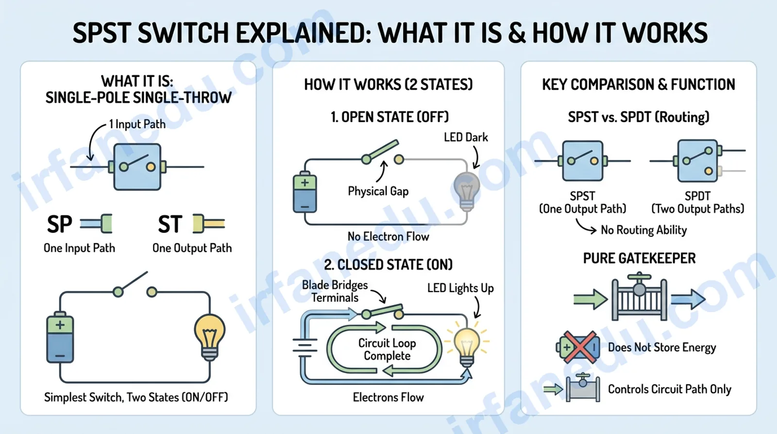
State 1 — Switch Open (OFF): The blade inside the switch is not touching terminal B. The circuit has a physical gap. No electrons can flow. The LED stays dark. Current = 0 A.
State 2 — Switch Closed (ON): You press the button. The blade physically bridges terminal A and terminal B. The circuit is now a complete loop. Electrons flow from the battery, through the switch, through the LED, and back. The LED lights up. Current flows.
Key observation: The switch has exactly one input path (terminal A) and one output path (terminal B). It can only be in one of two states: open or closed. That is the definition of SPST — you just lived it before I named it.
Notice that the switch itself does not generate or store energy. It is purely a gatekeeper — it decides whether the path for current exists or not. This is a subtle but important point I will return to in the Unique Insight section.
An SPST (Single-Pole Single-Throw) switch is the simplest electrical switch. It has one input terminal and one output terminal, and it controls a single circuit by either completing it (ON/closed) or breaking it (OFF/open). A standard household light switch is a classic SPST example. It has exactly two states and zero routing ability.
⚡ In Short
- 🔌 SPST = Single-Pole (one input) + Single-Throw (one output position).
- 💡 Closed = circuit complete = current flows. Open = circuit broken = no current.
- 🏠 Your wall light switch, flashlight button, and power-strip switch are all SPST.
- 🔄 SPST differs from SPDT: SPDT routes to one of two outputs; SPST is pure on/off.
- 📐 The schematic symbol is two dots (terminals) with an angled or straight blade between them.
- ⚠️ Always check voltage/current ratings — SPST switches are not all interchangeable.
What Is an SPST Switch?
An SPST switch — short for Single-Pole Single-Throw — is an electrical switch with one input terminal (the pole) and one output terminal (the throw). It controls a single circuit by physically connecting or disconnecting those two terminals. When the switch is closed, current flows; when it is open, current stops. It is the most fundamental switch type in electronics.
Let me break down the name so it sticks:
- Single-Pole: “Pole” refers to the number of separate input circuits the switch controls. Single-Pole means it controls exactly one circuit. There is one moving blade and one input terminal.
- Single-Throw: “Throw” refers to the number of output positions the blade can connect to. Single-Throw means the blade has only one landing spot — either it connects there (ON) or it does not (OFF).
Put those together: one input, one output, two states. That is the entire SPST switch in one sentence.
In my experience, students confuse “pole” and “throw” because the words sound interchangeable. Here is the mental model I give them: the pole is the source side (how many circuits are coming in), and the throw is the destination side (how many places the current can go). An SPST has one source and one destination. An SPDT has one source and two destinations. Once you see it that way, the whole SP/DP/ST/DT naming system becomes obvious.
Quick Facts: SPST Switch at a Glance 📊
| Property | Value / Description |
|---|---|
| Full Name | Single-Pole Single-Throw |
| Number of Poles (inputs) | 1 |
| Number of Throws (outputs) | 1 |
| Number of States | 2 (Open / Closed) |
| Number of Terminals | 2 (Terminal A and Terminal B) |
| Function | On/Off control of a single circuit |
| Common Voltage Ratings | 5V DC (logic), 12V DC (automotive), 120/240V AC (mains) |
| Schematic Symbol | Two dots with an angled or straight blade |
| Everyday Examples | Wall light switch, flashlight button, power strip switch |
| Related Switch Types | SPDT, DPST, DPDT |
How Does an SPST Switch Work?
An SPST switch works by physically moving a conductive blade (also called an armature or contact) to either bridge or separate two terminals. When the blade bridges the terminals, the circuit is complete and current flows. When the blade is lifted away, the circuit is broken and current stops.
Here is the physics behind it:
- Closed state: The blade is a conductor (usually copper or silver alloy). When it touches both terminals, it provides a low-resistance path. Electrons flow from the power source, through terminal A, across the blade, out terminal B, and on to the load.
- Open state: The blade is lifted away from one terminal. There is now an air gap in the circuit. Air is an insulator — its resistance is effectively infinite. No current flows regardless of the voltage applied (within safe limits).
The mechanical action varies by switch type — toggle switches use a lever, push-button switches use a spring-loaded plunger, rocker switches use a pivot — but the underlying principle is always the same: a physical conductor either bridges or separates two terminals.
Circuit: A 9 V battery, an SPST switch, and a 180 Ω resistor wired in series.
Question: What is the current when the switch is closed? What is the current when it is open?
Switch Closed (ON): The circuit is complete. Using Ohm’s Law: I = V ÷ R = 9 V ÷ 180 Ω = 0.05 A (50 mA).
Switch Open (OFF): The circuit is broken. The resistance of the air gap is effectively infinite. I = V ÷ ∞ = 0 A. No current flows.
Takeaway: The switch does not change the voltage of the battery or the resistance of the resistor. It simply controls whether a complete path exists for current to flow.
Reading an SPST Switch in a Circuit Diagram 📐
The schematic symbol for an SPST switch is one of the first symbols you learn in any physics or electronics course. Once you recognise it, you can trace current flow through any basic circuit.
  OPEN STATE (OFF) — Circuit Broken
  ─────────────────────────────────
  +9V ──┬── [SW: A  /  B] ──── [R: 180Ω] ──┬── GND
        │      ↑ blade angled away           │
        │      (gap = no current)            │
        └────────────────────────────────────┘
  Current = 0 A   |   Bulb/LED = OFF

  CLOSED STATE (ON) — Circuit Complete
  ─────────────────────────────────────
  +9V ──┬── [SW: A──B] ──── [R: 180Ω] ──┬── GND
        │      ↑ blade connects A to B    │
        │      (path = current flows)     │
        └─────────────────────────────────┘
  Current = 50 mA   |   Bulb/LED = ON
SPST switch in open (OFF) and closed (ON) states — ASCII circuit diagram
How to Read an SPST Switch in 5 Steps
- Locate the switch symbol — find two small circles (terminals) connected by a line (the blade) in the schematic. The blade may be angled (open) or straight (closed).
- Check the blade angle — blade angled away from the second terminal = open (OFF). Blade connecting both terminals in a straight line = closed (ON).
- Trace the circuit path — follow the wire from the power source through terminal A, across the blade, out terminal B, and on to the load.
- Identify the load — the component after the switch (bulb, motor, LED, resistor) is the load. When the switch closes, current reaches the load and it activates.
- Confirm the return path — trace the wire from the load back to the negative terminal of the power source to confirm the circuit is a complete loop.
[IMAGE: Labelled SPST schematic symbol showing terminal A, terminal B, blade in open and closed positions | ALT: SPST switch schematic symbol open and closed states labelled diagram]
Real-World Examples of SPST Switches 🌍
SPST switches are everywhere. You interact with them dozens of times a day without thinking about it. Here are the most common examples, grouped by setting:
At Home
- Wall light switch: The classic example. One flip closes the circuit (light on) or opens it (light off). Single circuit, two states — SPST.
- Power strip on/off switch: Controls whether mains power reaches the strip’s outlets. One input (the wall socket), one output (the strip) — SPST.
- Lamp toggle switch: The small switch on a bedside lamp cord works identically to a wall switch.
In Electronics & Gadgets
- Flashlight push-button: Press = closed = light on. Release = open = light off. The spring returns the blade to the open position.
- Computer power button (momentary SPST): Technically a momentary SPST — it closes only while held, then springs back open. The motherboard detects the brief closure and handles the rest.
- Keyboard keys: Every key on a mechanical keyboard is a momentary SPST switch. Press = closed = signal sent. Release = open = signal stops.
In Automotive & Industrial Settings
- Car interior light switch: The switch triggered when you open a car door is an SPST — door open = circuit closed = light on.
- Industrial machine guard switches: Safety interlock switches on machine guards are often SPST — guard removed = circuit open = machine stops.
One thing I always tell students: the SPST switch is not just a beginner concept you leave behind. Every time you design a circuit — even a complex one — you are almost always using SPST logic at the fundamental level. The more advanced switch types (SPDT, DPDT) are just multiple SPST mechanisms bundled together and operated by a single actuator. Master the SPST and you have the conceptual foundation for all of them.
SPST vs. SPDT: What Is the Difference? 🔄
The SPDT (Single-Pole Double-Throw) switch is the next step up from the SPST. Understanding the difference is essential for any student moving beyond basic circuits.
An SPDT switch has one input terminal (same as SPST) but two output terminals instead of one. The blade can connect the input to either output A or output B — but never both at once. This makes it a routing switch, not just an on/off switch.
| Feature | SPST Switch | SPDT Switch |
|---|---|---|
| Full Name | Single-Pole Single-Throw | Single-Pole Double-Throw |
| Number of Poles | 1 | 1 |
| Number of Throws | 1 | 2 |
| Number of Terminals | 2 | 3 |
| States | ON or OFF | Position A or Position B |
| Primary Function | On/Off control | Circuit routing / changeover |
| Can Turn a Circuit Fully Off? | Yes (open state) | Only if one throw is left unconnected |
| Typical Use | Light switch, flashlight | Staircase light (2-way), motor direction |
| Complexity | Simplest | One step more complex |
The staircase light is the classic SPDT example: two switches (one at the top of the stairs, one at the bottom) each wired as SPDT, connected together so either switch can turn the light on or off regardless of the other’s position. You cannot do that with SPST switches alone.
Almost every guide defines an SPST switch as “an on/off switch” and stops there. But here is what that framing misses: the SPST switch is not a binary device — it is a resistance-state device.
In the ideal model (what textbooks show), a closed SPST has zero resistance and an open SPST has infinite resistance. In reality, every physical SPST switch has a small but non-zero contact resistance when closed (typically 0.01 Ω to 0.1 Ω for quality switches) and a large but finite off-state leakage when open. For most classroom circuits this is irrelevant. But in high-current applications — say, a 50 A automotive relay — even 0.05 Ω of contact resistance dissipates 125 W of heat (P = I²R = 50² × 0.05), which can melt the contacts over time.
This is why switch datasheets specify both contact resistance and rated current — and why “just use any SPST switch” is bad advice in real engineering. When you see a switch rated “10A/125VAC”, that rating is not about the switch surviving the voltage — it is about the contact resistance staying low enough at that current that the switch does not overheat and weld its contacts shut.
In my experience teaching electronics, students who understand contact resistance make far fewer mistakes when they move from breadboard experiments to real-world circuit design.
Common Mistakes Students Make With SPST Switches ❌
After years of grading circuit diagrams and lab reports, I have seen the same errors come up repeatedly. Here are the most common ones — and how to fix them.
Students often assume “open” means the switch is open for business (i.e., ON). It is the opposite. An open circuit means the path is broken — no current flows. A closed circuit means the path is complete — current flows. Think of a door: an open door lets people through; an open switch does NOT let current through.
In a series circuit, it does not matter electrically where the switch sits — before or after the load — because the same current flows through every component. But in practice, safety standards require the switch to interrupt the live (positive/hot) wire, not the neutral/return wire. Always place the switch on the source side of the load in real-world wiring.
If you need to control a circuit from two locations (like a staircase light), two SPST switches wired in series will NOT work — you will only be able to turn the light off when both switches are open, which is not useful. You need two SPDT switches wired in a traveller configuration. Recognising when a task requires routing (SPDT) vs. simple on/off (SPST) is a key skill.
A 5V/1A SPST switch from a hobby kit will not safely control a 120V/10A mains circuit. The voltage and current ratings on a switch are maximum safe operating values — exceeding them causes arcing, contact welding, and fire risk. Always match the switch rating to the circuit’s voltage and current.
Practice Problems: Test Your Understanding 🧪
Work through each problem, then click to reveal the answer and explanation.
Problem 1: A 6V battery is connected in series with an SPST switch and a 120Ω resistor. The switch is closed. What is the current in the circuit?
Answer: 0.05 A (50 mA)
Using Ohm’s Law: I = V ÷ R = 6 V ÷ 120 Ω = 0.05 A. When the SPST switch is closed, it acts as a zero-resistance conductor, so the only resistance in the circuit is the 120 Ω resistor.
Problem 2: The same circuit has the switch opened. What is the current now? What is the voltage across the switch terminals?
Current = 0 A. Voltage across the switch = 6 V.
When the switch is open, the circuit is broken. No current flows (I = 0 A). Because no current flows through the resistor, there is no voltage drop across it (V = IR = 0 × 120 = 0 V). By Kirchhoff’s Voltage Law, all of the battery’s 6 V appears across the open switch terminals.
Problem 3: A student wants to control a light from two different locations. They wire two SPST switches in series. Will this work as a two-way switch? Explain.
No — this will not work correctly as a two-way switch.
With two SPST switches in series, the light is ON only when both switches are closed simultaneously. Either switch can turn the light OFF (by opening), but neither switch alone can turn it back ON if the other is open. A true two-way (staircase) switching system requires two SPDT switches wired in a traveller configuration, so either switch can toggle the light regardless of the other’s position.
Problem 4: A switch is labelled “SPST NO”. What does “NO” mean, and what is the switch’s default state?
“NO” stands for Normally Open.
A Normally Open SPST switch is open (circuit broken, no current) in its default/resting state. Current only flows when the switch is actively actuated (pressed, toggled, etc.). This is the most common type — a doorbell button is a classic Normally Open SPST. The opposite is “NC” (Normally Closed), which is closed by default and opens when actuated.
Frequently Asked Questions About SPST
Sources & References
Written and fact-checked by Dr Irfan Mansuri. External links open in a new tab and are provided for further reading and verification.