
SPDT Toggle Switch: How It Works, How to Wire It, and Why It Matters
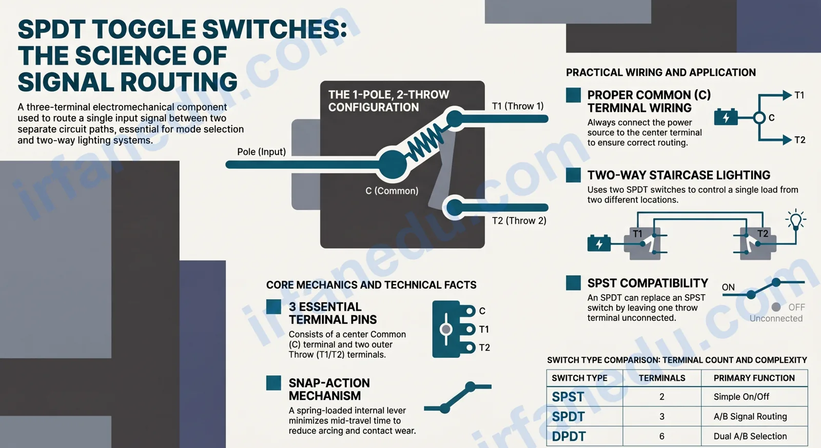
An SPDT toggle switch (Single Pole Double Throw) is a three-terminal electromechanical switch that connects one common input terminal to one of two output terminals at a time. Physically flipping the lever moves an internal contact from one output to the other, making it the standard component for routing a single signal or power source between two separate circuit paths.
The SPDT toggle switch is one of the most fundamental components in electronics and physics. It appears in everything from bedroom light circuits to aircraft cockpit panels. Understanding how it works gives you a solid foundation for reading circuit diagrams, building projects, and answering exam questions on switches, circuits, and electrical routing.
In this guide, I walk you through exactly what an SPDT switch is, how its internal mechanism works, how to wire one correctly, and where you will encounter it in real life. I also cover the mistakes students most often make when drawing or analyzing SPDT circuits, including one that even many textbooks get subtly wrong.
- Understand the three terminals and what each one does
- Read and draw the correct SPDT circuit symbol
- Wire an SPDT switch step by step
- Compare SPDT to SPST and DPDT switches
- Identify real-world applications in everyday devices
An SPDT (Single Pole Double Throw) toggle switch is a three-terminal switch that connects one common input to one of two output terminals at a time. Flipping the lever disconnects the common from the current output and connects it to the other. It is used to route a single signal or power source between two separate circuits, making it ideal for two-way switching applications.
Quick Facts: SPDT Toggle Switch at a Glance
| Property | Detail |
|---|---|
| Full name | Single Pole Double Throw |
| Number of terminals | 3 (Common, Terminal 1, Terminal 2) |
| Number of poles | 1 |
| Number of throws | 2 |
| Switch action | Routes C to T1 or C to T2 (never both at once) |
| Common circuit symbol | A lever arm pivoting between two contact points |
| Typical voltage range | 5 V (logic) to 250 V AC (mains-rated models) |
| Common uses | Two-way lighting, signal routing, A/B selection, mode switching |
| Can replace SPST? | Yes (leave one throw unconnected) |
Why the SPDT Switch Matters in Physics and Electronics
The SPDT switch is the simplest example of a routing switch in circuit theory. Unlike an on/off switch, it does not just break a circuit. It actively redirects current from one path to another. That distinction matters because it introduces students to the concept of circuit state: the same input can produce two different outputs depending on switch position.
In physics courses, SPDT switches appear in lessons on series and parallel circuits, logic gates (where they model a multiplexer), and electromagnetism labs. On standardized tests, questions about SPDT switches test whether you understand that the common terminal is always connected to something. There is no fully open state in a standard SPDT switch unless the lever is mid-travel during the physical throw.
SPDT switches appear in high school physics labs, electronics courses, robotics competitions, and university circuit analysis. Knowing the difference between a pole and a throw is a foundational skill that makes every more complex switch type (DPDT, rotary, relay) immediately understandable.
How Does an SPDT Toggle Switch Work?
An SPDT toggle switch works by moving a single conductive lever arm (the “pole”) between two fixed contact points (the “throws”). The lever is always in contact with exactly one of the two throws at any given resting position.
Inside the switch body, three metal terminals extend through the housing. The center terminal is the Common (C). The two outer terminals are Throw 1 (T1) and Throw 2 (T2). A spring-loaded rocker or lever mechanism holds the contact firmly against one throw until you apply enough force to flip it to the other. The spring prevents the contact from resting in a mid-position, which would create an open circuit.
The Internal Mechanism Step by Step
- Lever at Position 1: The conductive arm bridges C and T1. Current flows from C through the arm to T1. T2 is open (disconnected).
- Force applied to lever: You push the toggle. The spring-loaded mechanism compresses and the arm lifts off T1.
- Mid-travel (momentary open): For a fraction of a second, the arm touches neither T1 nor T2. This is the only instant the circuit is fully open.
- Lever snaps to Position 2: The spring drives the arm onto T2. Current now flows from C through the arm to T2. T1 is open.
- Stable state: The switch rests firmly at Position 2 until flipped again.
The key physical principle is the snap-action mechanism. The spring stores energy as you push the lever, then releases it suddenly, snapping the contact to the new position. This minimizes the time the contact spends in mid-travel, which reduces arcing and contact wear.
  POSITION 1 (C connected to T1)        POSITION 2 (C connected to T2)

       T1 o---[contact]                       T1 o
              |                                      \
       C  o---+  (lever arm)              C  o---+    (lever arm)
                                                  |
       T2 o   (open)                       T2 o---[contact]

  Legend:
    o   = terminal pin
    --- = electrical connection (current flows)
    [contact] = conductive lever touching the throw terminal
    (open) = no connection, circuit broken at that terminal
What Does the SPDT Circuit Symbol Look Like?
The standard SPDT circuit symbol shows a lever arm (a diagonal line) pivoting from the Common terminal toward one of two contact points. The arm is drawn touching one throw to show the current switch state.
         T1
          o
         /
        /  <-- lever arm (shown in Position 1)
  C ---o
        \
         o
         T2

  Reading the symbol:
    C  = Common terminal (always connected to the lever pivot)
    T1 = Upper throw contact (lever touching it = circuit C-T1 closed)
    T2 = Lower throw contact (lever away from it = circuit C-T2 open)

  In Position 2, the lever arm tilts DOWN to touch T2 instead.
When you see this symbol in a circuit diagram, the diagonal lever arm tells you which throw is currently active. If the arm points up, C connects to T1. If the arm points down, C connects to T2. Some textbooks draw both throws horizontally; the lever still pivots between them.
How to Wire an SPDT Toggle Switch
Wiring an SPDT switch correctly requires identifying the three terminals and deciding which circuit goes where. The process is the same whether you are wiring a 5 V LED circuit on a breadboard or a 12 V automotive accessory switch.
Step-by-Step Wiring Instructions
- Identify the Common terminal (C). On most toggle switches, the Common is the center pin of the three. Check the datasheet or use a multimeter in continuity mode: the Common will beep against both other terminals as you flip the lever.
- Connect your power source (or signal) to C. Run a wire from the positive supply rail or signal source to the C terminal. This is the input that will be routed.
- Connect Load A to Terminal 1 (T1). Wire the first load (e.g., a red LED with its resistor) from T1 back to ground.
- Connect Load B to Terminal 2 (T2). Wire the second load (e.g., a green LED with its resistor) from T2 back to ground.
- Complete the ground return. Both loads share the same ground (negative supply rail). This is a common point of confusion — you do not need two separate grounds.
- Test the switch. Flip to Position 1: Load A lights up, Load B is off. Flip to Position 2: Load B lights up, Load A is off.
If you only need one load and want on/off behavior, connect your load to T1 and leave T2 unconnected. The switch now behaves exactly like an SPST (on/off) switch. This is a legitimate wiring technique, not a workaround.
In my experience teaching circuit labs, the single biggest wiring error students make is connecting the load between T1 and T2 instead of between each throw and ground. They treat the two throws as if they are the two ends of a simple on/off switch. The result is that both loads are always in the circuit, just at different potentials, and neither behaves as expected. Always wire each throw independently back to ground.
SPDT vs. SPST vs. DPDT: Which Switch Do You Need?
Switch nomenclature follows a consistent pattern: the first part (SP, DP) tells you how many poles (independent circuits the switch controls), and the second part (ST, DT) tells you how many throws (output positions per pole). Here is how the three most common types compare.
| Feature | SPST | SPDT | DPDT |
|---|---|---|---|
| Full name | Single Pole Single Throw | Single Pole Double Throw | Double Pole Double Throw |
| Number of terminals | 2 | 3 | 6 |
| Circuits controlled | 1 | 1 (routed to 2 outputs) | 2 (each routed to 2 outputs) |
| Function | On / Off | A / B selection | Dual A / B selection |
| Can replace SPST? | N/A | Yes (leave one throw open) | Yes (use one pole only) |
| Typical use | Simple on/off light switch | Two-way lighting, A/B signal routing | Motor direction reversal, stereo signal routing |
| Complexity | Simplest | Moderate | Most complex of the three |
The SPDT is the most versatile of the three for general-purpose use. Because it can replace an SPST but also do more, many engineers default to SPDT when they are unsure which they will need during prototyping.
If you are studying circuits as part of a broader physics course, my guide on Tension in Two Strings at Different Angles covers another core physics concept you will encounter alongside circuits.
Real-World Applications of the SPDT Toggle Switch
The SPDT switch is everywhere once you know what to look for. Its ability to route one input to one of two outputs makes it the right choice whenever a device needs to switch between two modes, sources, or destinations.
Everyday Devices That Use SPDT Switches
- Two-way staircase lighting: Two SPDT switches at the top and bottom of a staircase let you turn the light on or off from either location. This is the classic “traveler wire” circuit taught in every electrical wiring course.
- Automotive accessories: Dashboard toggle switches for fog lights, auxiliary fans, and winches are almost always SPDT or DPDT. The Common connects to the battery feed; the two throws connect to different accessories or speed settings.
- Guitar amplifiers: The channel-select footswitch on a two-channel amp is an SPDT switch routing the guitar signal to either the clean or distortion preamp channel.
- Arduino and microcontroller projects: SPDT switches select between two input modes (e.g., manual vs. automatic control) or two sensor inputs without needing any software logic.
- Radio equipment: Antenna switches route a transceiver to one of two antennas, preventing both from being connected simultaneously.
- Test equipment: Oscilloscopes and multimeters use rotary SPDT-style mechanisms to select measurement ranges.
Scenario: You are building a simple robot that can run either a red warning LED or a green status LED, but never both at once. You have a 9 V battery, two LEDs, two 470-ohm resistors, and one SPDT toggle switch.
Solution: Connect the 9 V positive rail to C. Wire the red LED (with its 470-ohm resistor) from T1 to ground. Wire the green LED (with its 470-ohm resistor) from T2 to ground. Flip the switch to T1 for red, T2 for green. The SPDT guarantees only one LED is powered at any moment, with no risk of both being on simultaneously.
SPDT Wiring Configurations Compared
The same physical SPDT switch can be wired in several different ways depending on what you need it to do. Here is a comparison of the four most common configurations.
| Configuration | How Wired | Behavior | Best For |
|---|---|---|---|
| Standard A/B routing | Power to C; Load A to T1; Load B to T2 | Selects between Load A and Load B | Two-LED indicator, dual-mode circuits |
| On/Off (SPST mode) | Power to C; Load to T1; T2 unconnected | T1 position = on; T2 position = off | Simple on/off when only SPDT is available |
| Two-way (staircase) lighting | Two SPDT switches; travelers connect T1-T1 and T2-T2; power to C of Switch 1; load to C of Switch 2 | Either switch toggles the light on or off | Hallway / staircase lighting from two locations |
| Signal inversion / polarity flip | Signal to C; T1 = normal output; T2 = inverted/reversed output | Flips signal polarity or phase | Audio phase switching, DC motor direction (with DPDT) |
Common Mistakes Students Make with SPDT Switches
Most errors with SPDT switches fall into one of three categories: misidentifying terminals, misreading the circuit symbol, or confusing poles with throws. Here are the most frequent ones I see, with the correct approach alongside each.
| Mistake | What Goes Wrong | Correct Approach |
|---|---|---|
| Wiring load between T1 and T2 | Both terminals are at different potentials; load behavior is unpredictable | Wire each load from its throw terminal independently back to ground |
| Treating SPDT as always-open | Student assumes both throws are open when the switch is “off” — there is no off state | Remember: C is always connected to one throw. The only open is the unused throw. |
| Confusing poles and throws | Student thinks “Double Throw” means two separate circuits are controlled | Poles = number of independent circuits. Throws = number of positions per pole. SPDT has 1 pole, 2 throws. |
| Misidentifying the Common terminal | Power connected to T1 or T2 instead of C; circuit only works in one lever position | Use a multimeter in continuity mode: the Common beeps against both other terminals as you flip the lever |
| Drawing the symbol with the lever disconnected from C | Schematic implies the switch can be fully open, which is incorrect for a standard SPDT | The lever pivot must always be drawn touching the C terminal; only the free end moves between T1 and T2 |
The SPDT switch is not the same as a “changeover switch” in all contexts, and this distinction costs students marks.
Most textbooks and online guides use “SPDT” and “changeover switch” interchangeably, and in most hobby circuits that is fine. But in industrial and IEC-standard electrical engineering, a “changeover switch” specifically implies a make-before-break action: the new contact is made before the old one is released, so there is a brief moment when C connects to both T1 and T2 simultaneously. A standard SP
Sources & References
Written and fact-checked by Dr Irfan Mansuri. External links open in a new tab and are provided for further reading and verification.